This document describes how to create an inbound hierarchical interface using SKYVVA Batch mode with V3 SKYVVA connector module.
Our old SAP PO module is now enhanced to support the hierarchical message payload and the batch will also split the messages as small attachments as per our requirement.
For the batch splitting we just need to add a new parameter “BatchPacketSize” in the receiver channel configuration
Introduction
Batch data processing is an efficient way of processing high volumes of data, where a group of transactions is collected over a period of time. Data is collected, entered, processed and then the batch results are produced. So, now we are going to create an inbound interface using integrate batch with Skyvva connector module
Initially, we have to start with Salesforce Skyvva. This interface is also the same as “How to create an inbound interface to post a single sObject?” but few things to be added in Skyvva interface settings and in the module parameters configuration.
- SKYVVA interface creation
For the hierarchical interface we have to create parent child interface in skyvva.
Create an inbound interface, for example, “AccountContactIntegrateBatch” as shown below.
Account is the parent and contact is child
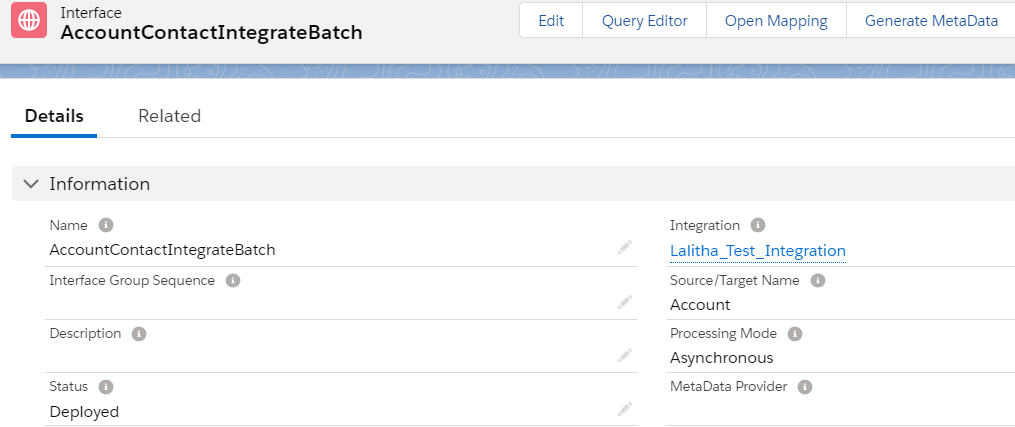
maximum integrate Batch size will be 5000
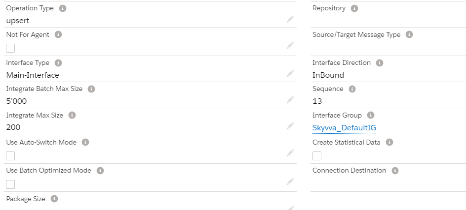
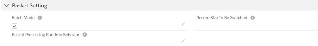
As we are using Batch mode So, we have to check the Bulk mode checkbox as shown below:
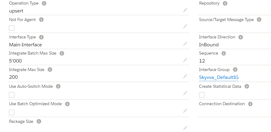
Create contact child interface
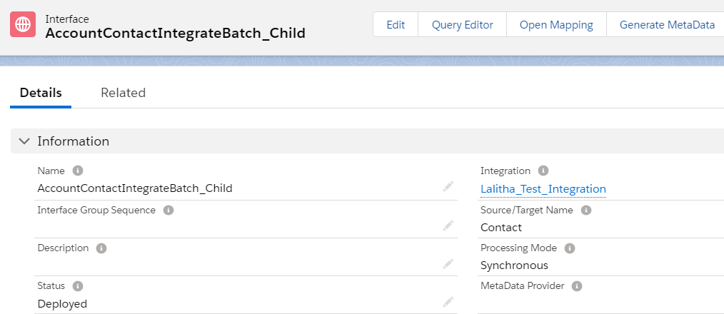
maximum integrate Batch size will be 5000
As we are using Batch mode So, we have to check the Bulk mode checkbox as shown below:
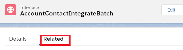
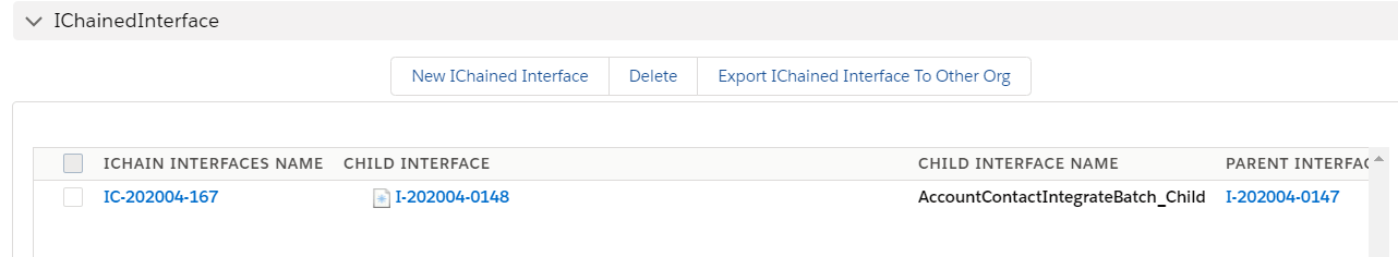
Now add the child interface as ichained interface in the parent interface related tab.
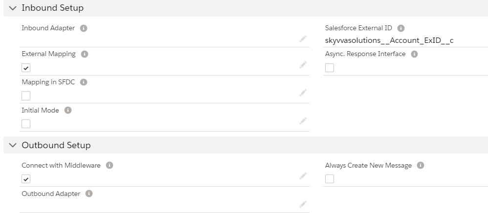
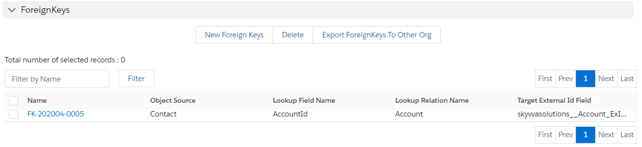
Add the foreign key in the child interface to link the Contact with Account.
Download the WSDL’s from the classic mode to do further mapping in SAP PO.
Step 3 – Import WSDL into ESR
First, we have to create a namespace in ESR like “urn:skyvva:ChainedIntegrateBatch”.
Now create an external definition under the namespace like below. Here the WSDL is for Account. So, we can give the name as “ED_AccountContact_IntegrateBatch”
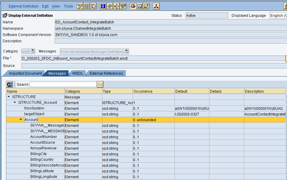
Import the WSDL and save and activate the external definition.
- Sender data type
Create sender data type as shown below
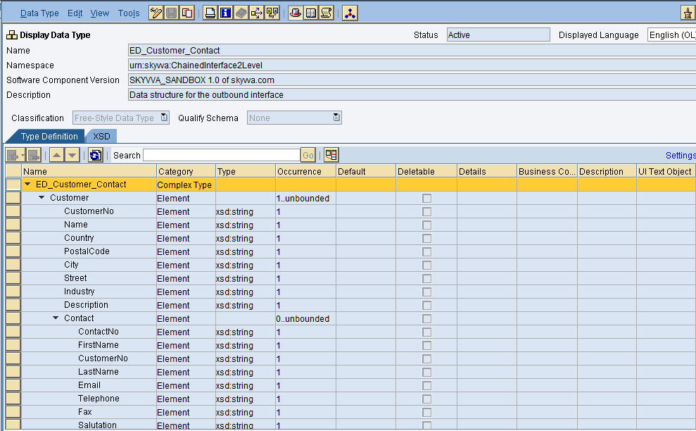
after creating the source data type click on save and activate.
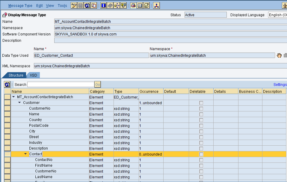
- Source message type
Create the message type as shown below:
- Outbound Service Interface
Create an Outbound service interface, in that select category as outbound and select the respective message type.
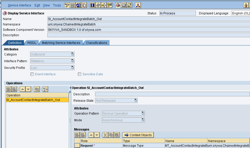
then save and activate the outbound service interface.
- Inbound Service Interface
Create an inbound service interface, in that select category as inbound and select the respective external definition.
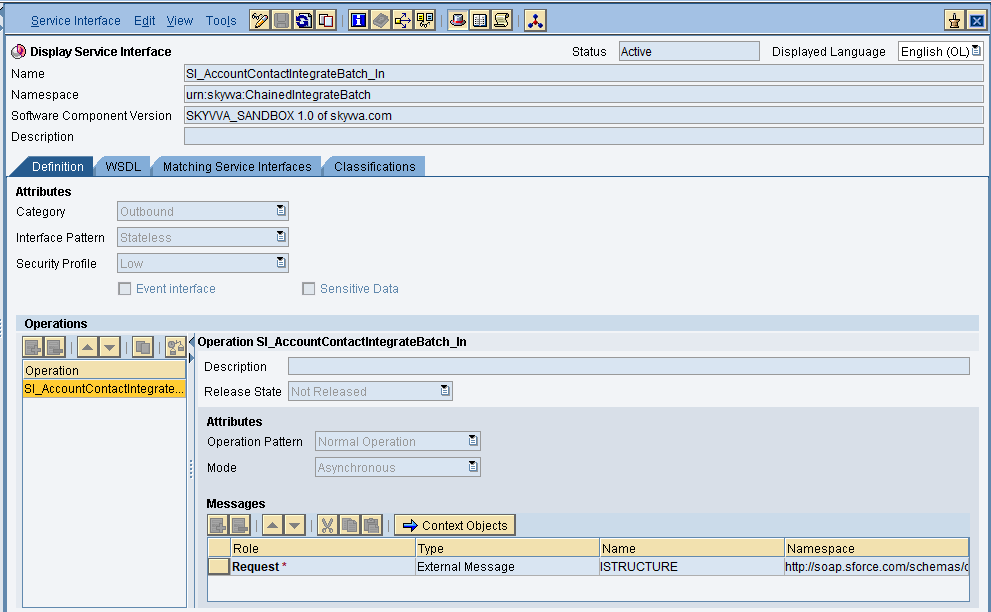
Save and active the inbound service interface.
- Message Mapping
Create message mapping as shown below:
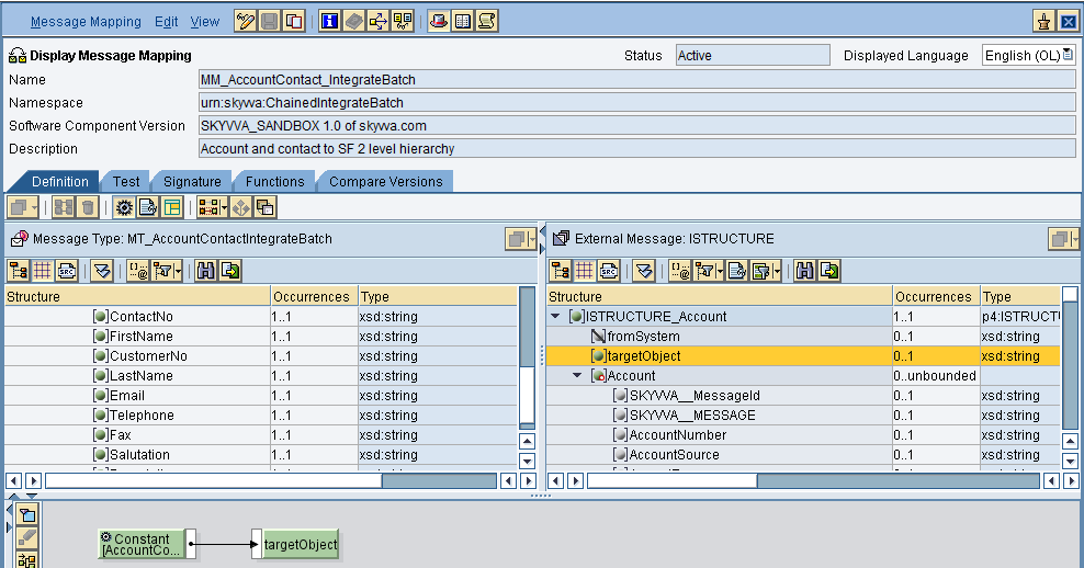
Insert the respective source and target structure and then do the mapping.
Now save and activate the message mapping.
- Operation Mapping
Create Operation mapping as shown below
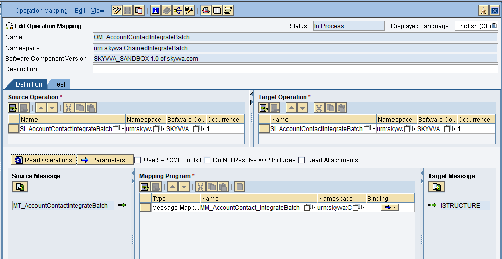
Select the respective outbound and inbound service interfaces and also the message mapping then save and activate the operation mapping.
Creation of Integrated Configuration Objects
After creating the objects in ESR. We have to configure these objects in the integration directory.
First, we have to create Configuration Scenario.
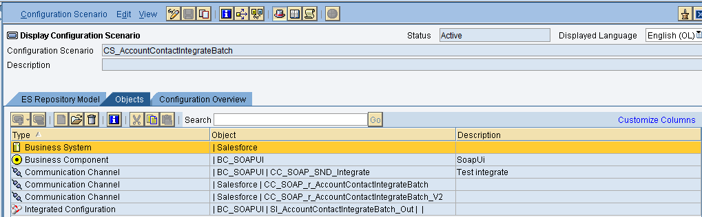
An Integration scenario has the following objects.
- Business System for Sender and Receiver
- Sender and Receiver Communication channel
- Integrated Configuration
These are the objects we should create.
We have to define our business system e.g. for the SAP-Backend. For Salesforce you can use our proposal “Salesforce” as the business system. We have to import these business systems from SLD.
Configuring the Sender SOAP communication channel
Create sender communication channel as shown below.
Since we are using SOAP UI as a source. So, here we are using SOAP in the sender channel.
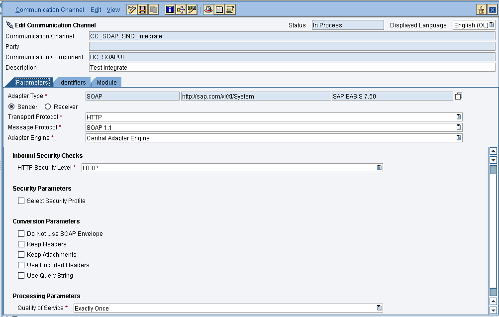
Provide the necessary details as shown and then save and activate the channel.
- Configuring the SOAP receiver channel
Configuration for Tab “General”
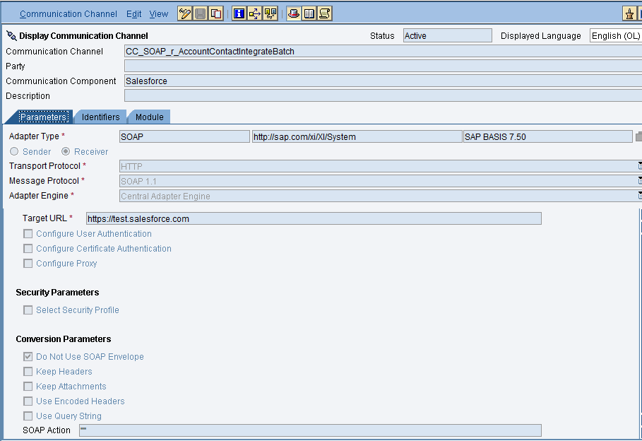
Specify the parameters as shown in the above screenshot.
Below is the configuration for the “Advanced” Tab.
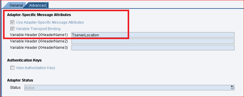
The value “TserverLocation” has to be entered for the parameter Variable Header (XHeaderName1).
Below are the settings for Tab “Module”. Here, the SKYVVA module containing the logic for session handling must be specified.
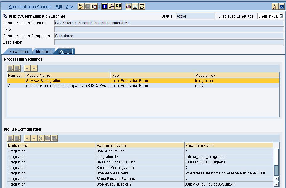

Configuration of module parameters are described in detail below
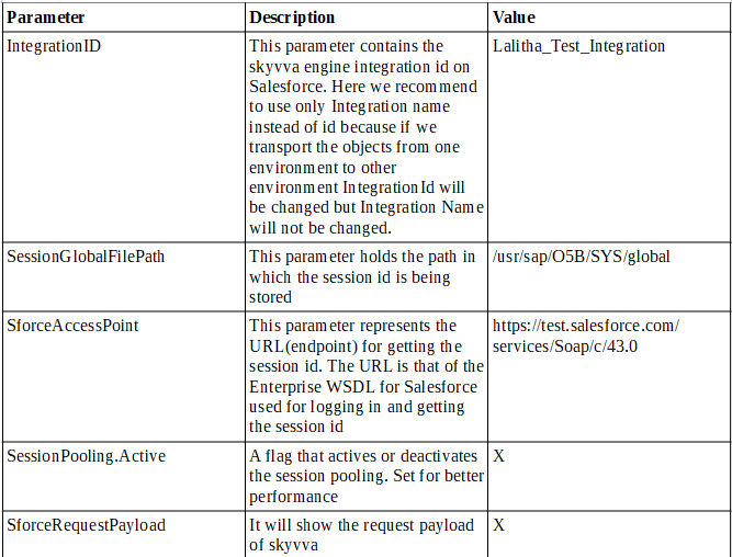
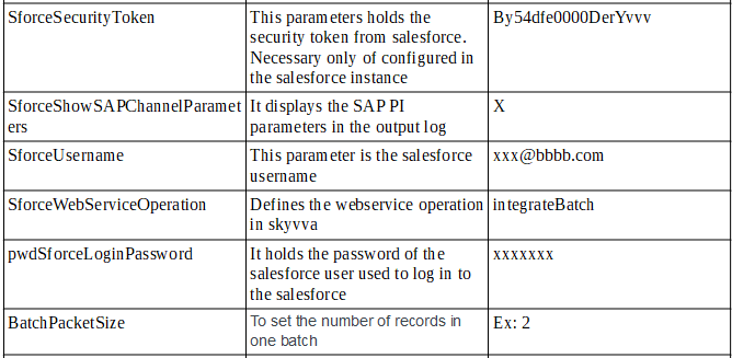
- SKYVVA Module Parameters
Integrated Configuration
Create integrated configuration objects as shown below.
Enter the required data e.g. the Communication Component, Interface and Namespace and then click on create button to create an ICO.
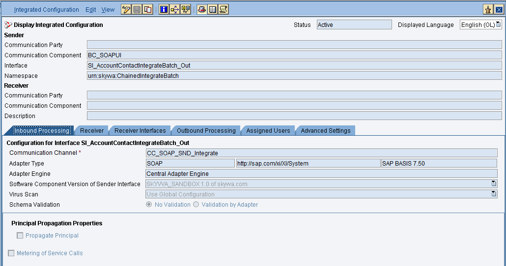
Now go through the tabs from left to right to configure the relevant objects. In this first tab “Inbound Processing” here we have to specify the sender communication channel.
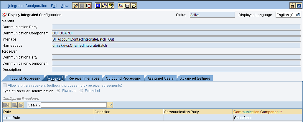
Here in the “Receiver” tab, we have to specify the receiver business system.
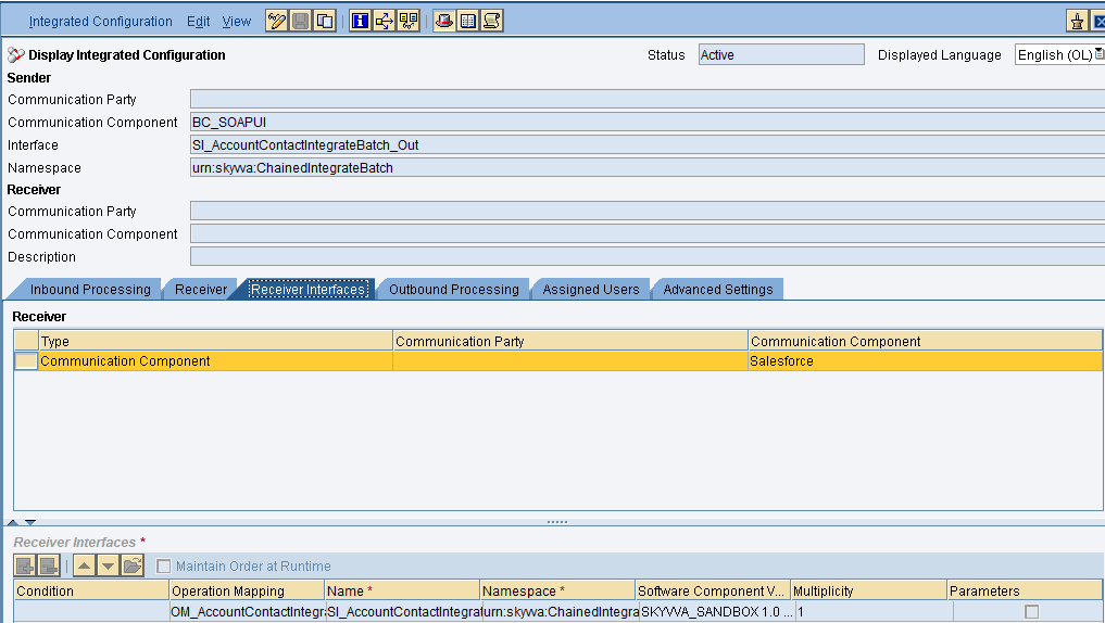
In Receiver interfaces tab specify the operation mapping.
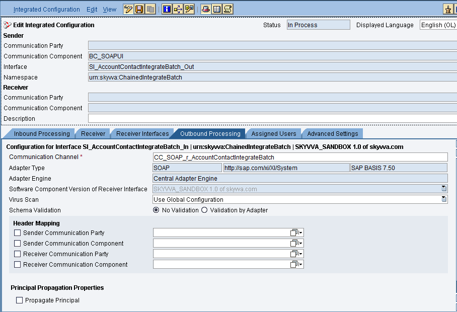
In the “outbound processing” tab, we have to specify the receiver channel.
- Test the Inbound Interface.
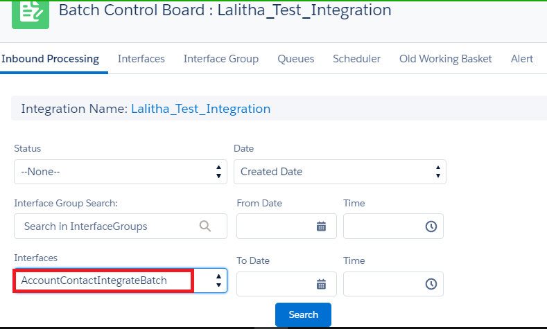
Triggering the data from the Source system. Now we have to check the result in Batch Control board as shown below.
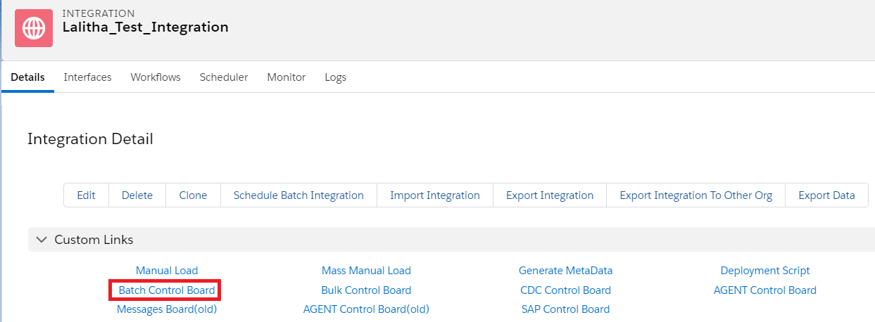
Here we have to select the Batch interface then click on search.
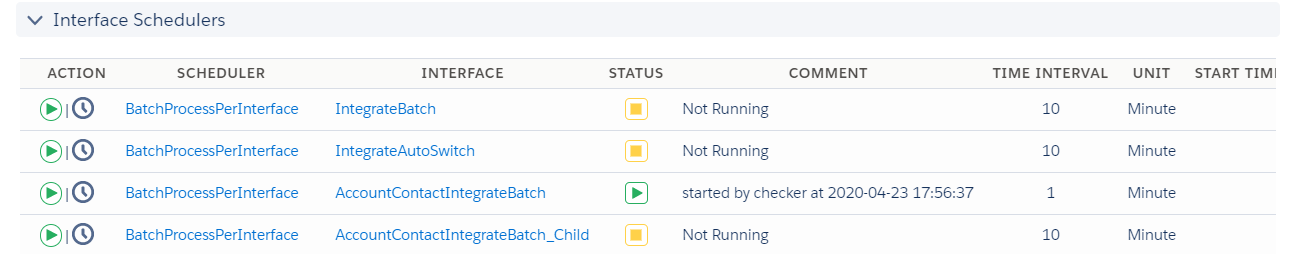
We have a scheduler to schedule the jobs during a particular time intervals.
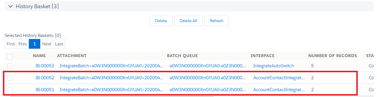
In the “History Basket” we can see the processed files as batch files as shown. We have sent 4 records with BatchPacketSize 2, So the file got splitted to two batches each contains 2 records.
Now the message processing completed. We can see the messages in message monitor.
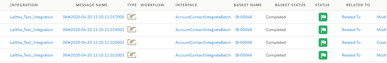
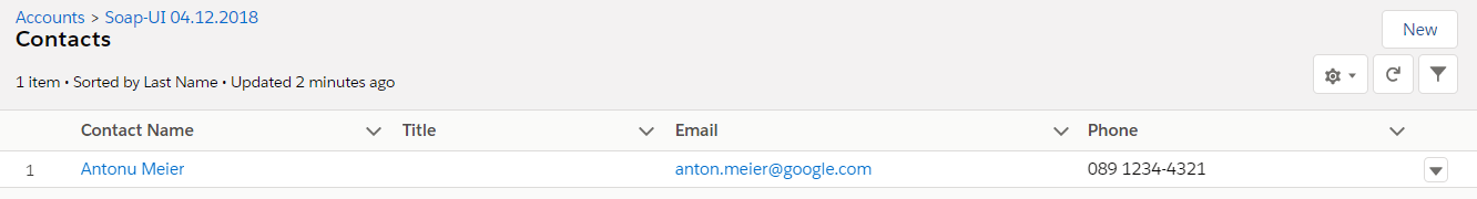
Click on related to to view the record
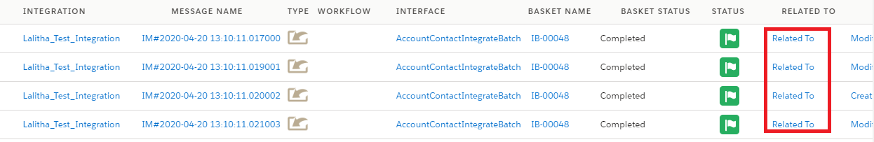
Here is the data which we sent from the source system.